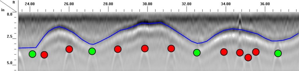
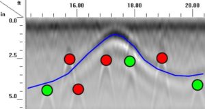
 PEX Tube in Elevation View; green and red dots highlight tied and untied rebar.
Concrete GPR mapped the location and depth of all PEX tubes in 6000 square feet of concrete slab with cutting edge 3D GPR techniques. The PEX tubing, used for radiant floor heating, was too shallow in many areas. Our findings enabled the general contractor to create a concise remediation plan without ripping out the entire slab.
Background
Design of the concrete floor slab in a new school building includes radiant heating with PEX tubing. When the forms were removed, the general contractor found PEX tubes were breaking the slab surface in several places. This triggered a series of questions, including:
- What caused / allowed the tubes to rise to the slab surface during the pour?
- Is the problem isolated to the visible areas or pervasive throughout the slab?
- Is it feasible to repair the issue, or does the entire slab need to be replaced?
- In a repair scenario, where are all of the “bad” areas actually located?
Ground Penetrating Radar Scope of Service
Original scope: Use real-time 2D linescanning to evaluate general PEX tube conditions and determine if issue is localized or pervasive.
Real-time linescanning determined that shallow tubes were spread unpredictably throughout the slab.
Modified scope: Use 3D GPR to map the location and depth (X,Y,Z) of all PEX tubes in the slab. Identify areas where the tube elevation is too shallow. Determine, if possible, factors which contributed to the PEX tube elevation problems.
GPR Methodology
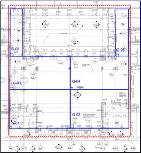
We subdivided the total slab area into six data collection grids, splitting off the two hallways and dividing the main room into four parts. High frequency ground penetrating radar data files were collected in both directions at precise intervals for each grid. We combined these data files to create highly accurate 3D models of the slab interior, depicting the rebar and PEX tubing in high detail. These 3D models were post-processed with position correction, bandpass filters, and range gain to highlight the key data. Our expert analysts then reviewed every inch of data to mark areas where the PEX tube elevation was too high. We also marked all rebar in the vicinity of these high points, to identify locations where the tube had been tied to rebar, and where it had not. With these details, we presented our findings to the general contractor in a variety of perspectives, including plan view diagrams of high points, elevation view slices of problematic tubes, comparative elevation view slices of tubes with acceptable depths, and detailed spreadsheets with the (X,Y,Z) values of all problematic tube locations.
Field Execution Challenges
One of our team’s greatest strengths is our ability to adapt and overcome challenges in the field, which allows us to maintain the highest data quality while keeping your project on schedule. Every project faces obstacles and this one was no exception. The most significant hurdle was simply the weather — Winter in the Pacific Northwest is always wet and cold, but January 2017 really tried to raise the bar. This building is part of a new construction project, and when began, there was very little barrier to the driving rain and sleet. The cold wet conditions don’t slow down our field crew, but they raise concerns for our digital GPR equipment…which is, essentially, a very expensive computer. The weather posed significant challenge keeping the slab clean. Windblown debris was only a part of the puzzle, the heavy rain also turned any dirt and sawdust into nice thick mud. Data collection ideally requires a clean, dry surface. We can work with moist concrete, but puddles and standing water obscure the data. Mud and muck reduce our ability to efficiently layout and collect precise data files, and they also force us to frequently stop and clean our equipment. While the general contractor focused on skinning the building and plugging the windows, our team blitzed, splitting between water control, site clean-up, and active data collection. With teamwork and experience, all data was collected in rapid time, and the job moved on to the office.
Findings
With comprehensive analysis of the data, our team answered all of the key concerns of the general contractor and enabled an efficient and cost-effective plan of remediation.
- What caused / allowed the tubes to rise to the slab surface during the pour?
- The PEX tubes floated to the surface during the pour due to several factors.
- The radiant heating system was filled with air, rather than water, during the pour.
- PEX tubing was not pulled taut before tying it to the rebar mat.
- PEX tubes were inconsistently tied to the rebar mat.
- The tubing was laid over near-surface rebar dowels at control joints.
- Is the problem isolated to the visible areas or pervasive throughout the slab?
- The problem is pervasive throughout the slab.
- Three areas of the slab have a high concentration of problem tubes.
- The remaining slab contains sporadic and unpredictable problem tubes.
- Is it feasible to repair the issue, or does the entire slab need to be replaced?
- Repair is feasible.
- Depth information for all problem tubes allows specific and limited targeting.
- In a repair scenario, where are all of the “bad” areas actually located?
- Details of all shallow tubing are provided in multiple formats:
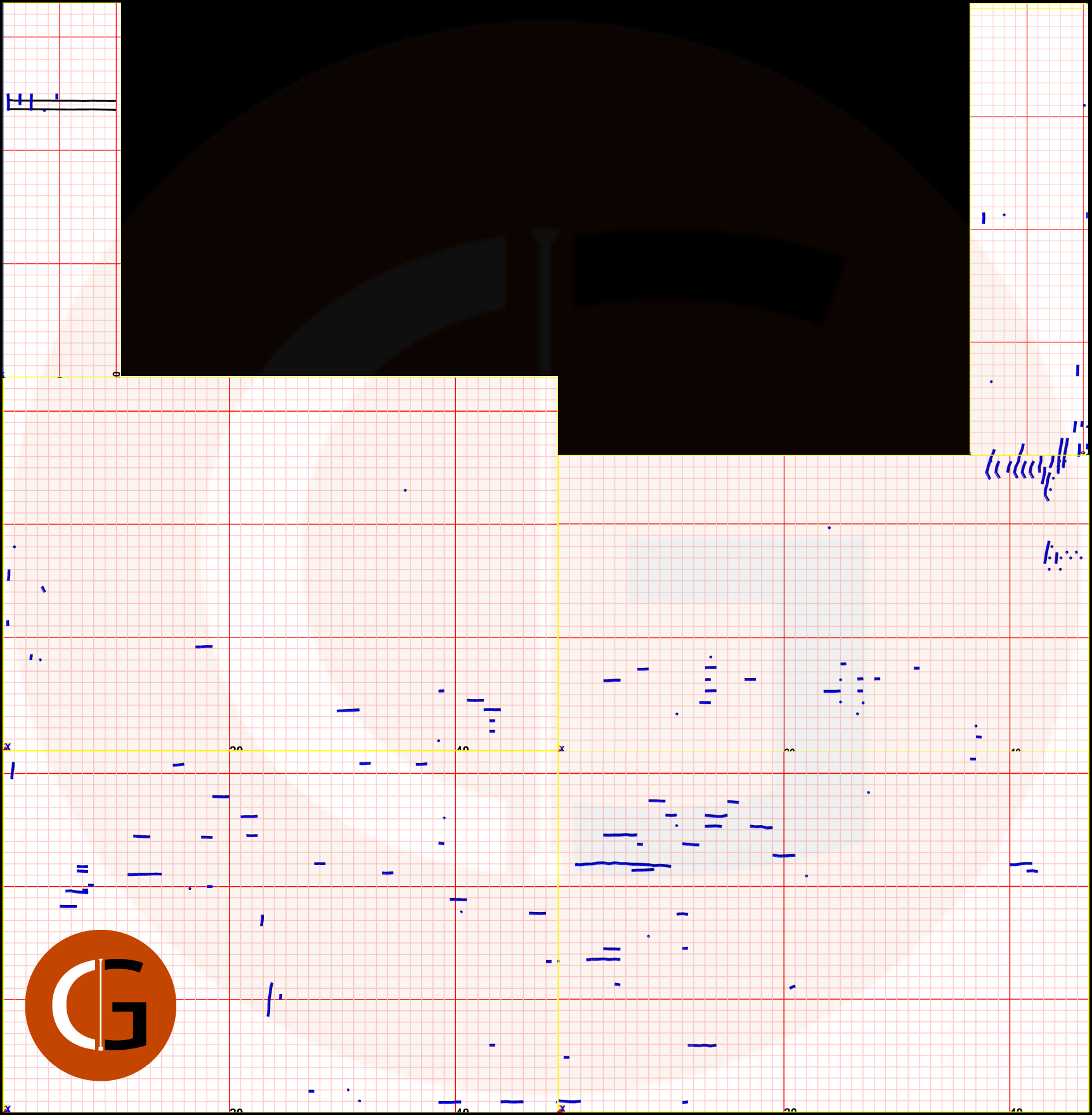
- Plan view
- Interactive plan view with depth details
- Elevation slices of key areas
- Numeric spreadsheet of location and depth (X,Y,Z) for all shallow tubes.
- Details of all shallow tubing are provided in multiple formats: